Understanding X/R Ratio in Power Systems: Why It Matters for Engineers
 Jeyakumar Velusamy
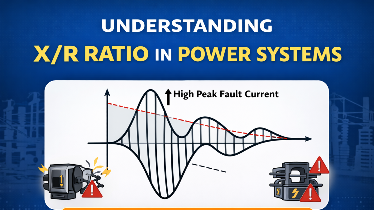
Understanding X/R ratio is key in power systems. It impacts fault current, breaker performance, and protection. Avoid costly design mistakes.
Introduction
In electrical power systems, especially in substation design and fault analysis, one critical parameter engineers must understand is the X/R ratio. Though it may seem like a simple concept, the X/R ratio plays a major role in equipment selection, protection design, and system safety.
This blog will break down the concept in a practical and easy-to-understand way.
What is X/R Ratio?
The X/R ratio is the ratio of:
Reactance (X) to
Resistance (R)
Mathematically:
X/R = Reactance / Resistance
Reactance (X): Opposition to current due to inductance
Resistance (R): Opposition to current due to heat losses
Why is X/R Ratio Important?
1. Fault Current Calculation
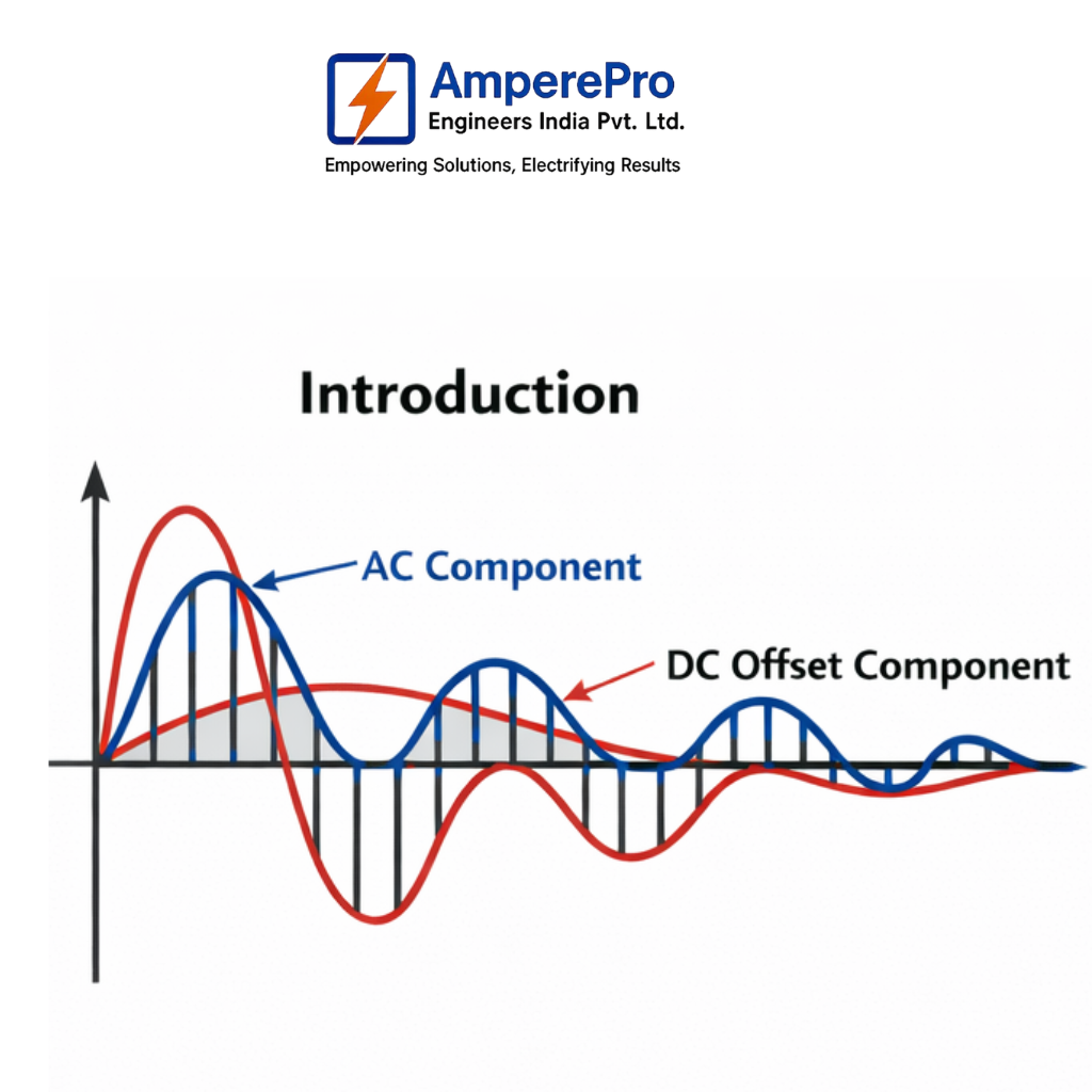
When a fault occurs in a power system, the current consists of:
AC component
DC offset component
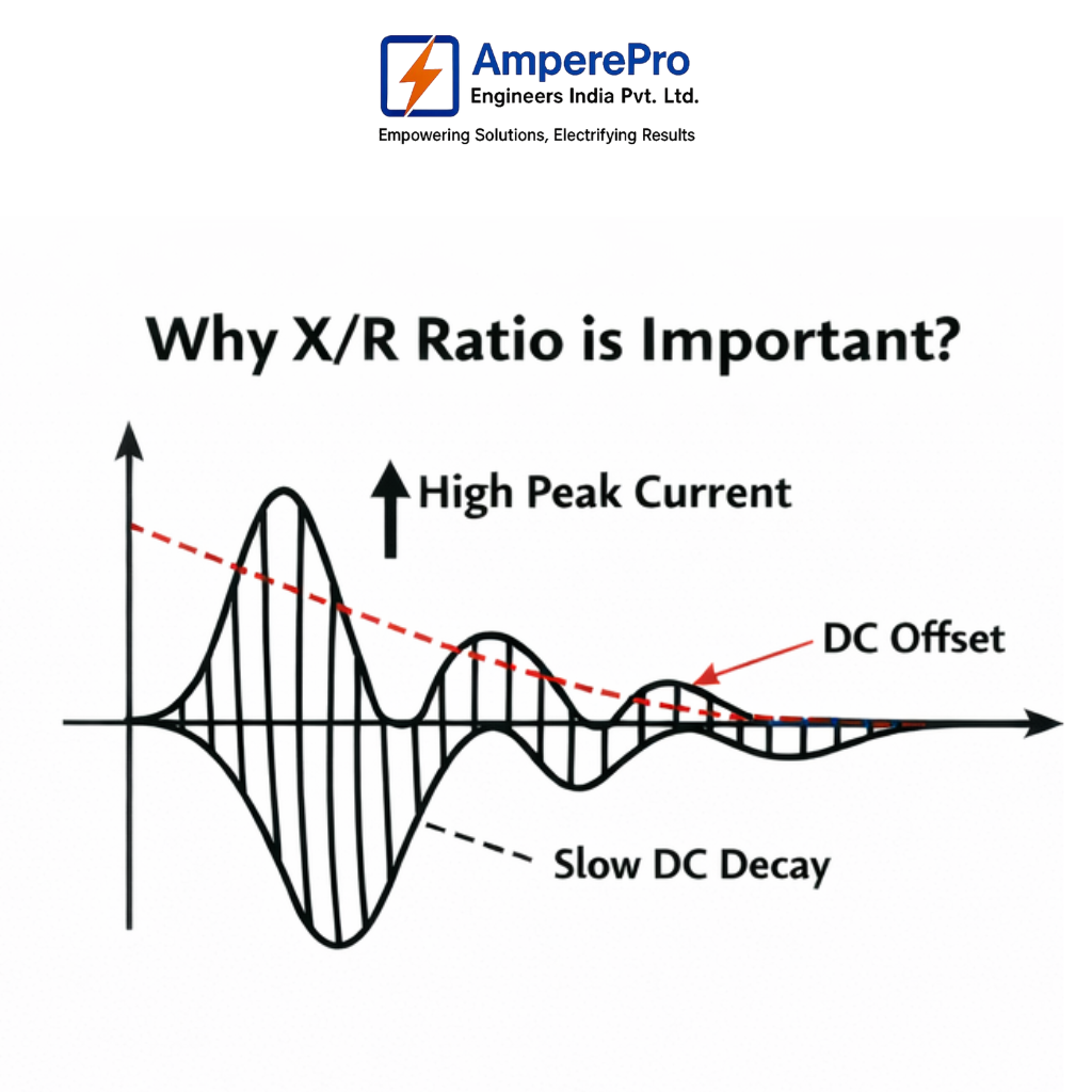
The X/R ratio determines how large the DC offset will be.
Higher X/R ratio = Higher DC offset
Higher DC offset = Higher peak fault current
2. Circuit Breaker Selection
Circuit breakers must withstand:
Symmetrical current
Asymmetrical current (with DC offset)
A higher X/R ratio increases the making current and breaking stress on breakers.
3. Protection System Design
Protective devices like relays depend on accurate current measurement.
High X/R ratio affects CT (Current Transformer) performance
Can cause CT saturation, leading to incorrect relay operation
4. Equipment Thermal & Mechanical Stress
High X/R ratio → Higher peak currents
Leads to increased mechanical forces on busbars and conductors
Also increases thermal stress
Typical X/R Ratio Values
System Element | X/R Ratio Range |
Transmission Lines | 10 - 20 |
Substations | 10 - 40 |
Generators | 20 - 200 |
Industrial Systems | 5 - 15 |
Real-World Example
Consider a substation fault:
If X/R = 5 → Lower DC component → Easier interruption
If X/R = 30 → High DC component → Circuit breaker must handle higher stress
This directly impacts:
Equipment rating
Cost
Safety margin
Impact on Fault Waveform
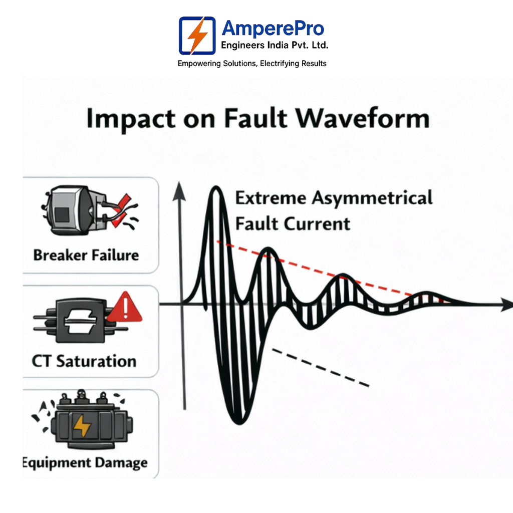
A higher X/R ratio results in:
Slower decay of DC component
Asymmetrical waveform
Higher peak current during first cycle
This is why engineers must consider X/R ratio during short circuit studies.
Where is X/R Ratio Used in Design?
Short Circuit Analysis
ETAP / Power System Simulation
Circuit Breaker Selection
CT & Relay Coordination
Earthing System Design
Common Mistakes to Avoid
Ignoring X/R ratio in fault studies
Using only symmetrical current values
Not checking breaker asymmetrical rating
Overlooking CT saturation issues
What Happens If You Ignore X/R Ratio? (Real Problems Engineers Face)
1. Wrong Circuit Breaker Selection
Problem:
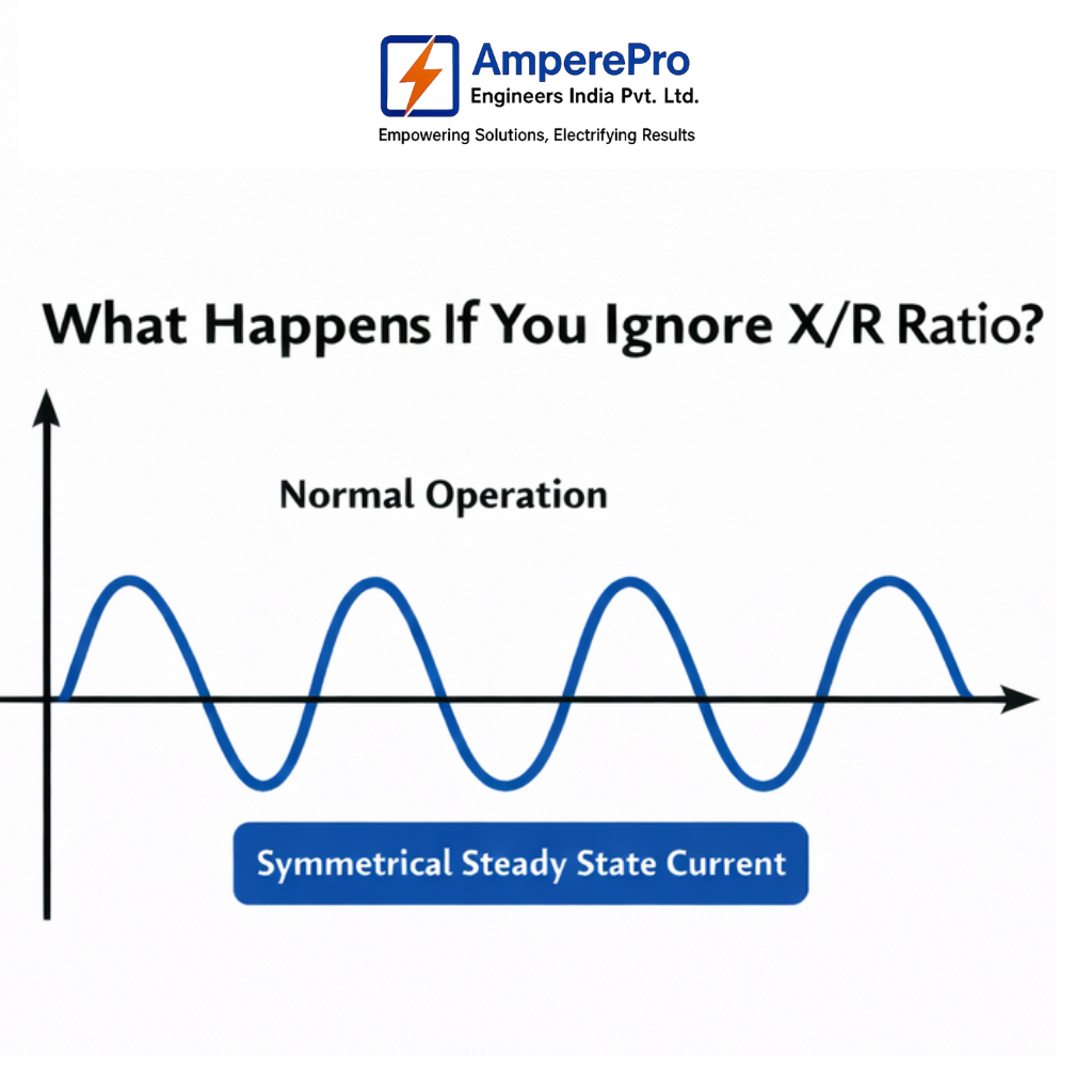
If you calculate only symmetrical fault current and ignore X/R ratio:
You underestimate peak (making) current
Breaker may not withstand fault
Result:
Breaker contact damage
Failure during fault interruption
Safety risk
Solution:
Always check asymmetrical current rating
Include X/R ratio in short circuit study
2. Underestimating Fault Current Peak
Problem:
High X/R ratio produces a large DC offset, increasing peak current.
If ignored:
Equipment is designed for lower stress
Result:
Busbar bending / mechanical damage
Conductor stress
Structural failure
Solution:
Use peak current calculation considering X/R
Verify mechanical withstand rating
3. CT Saturation & Relay Failure
Problem:
High X/R ratio → High DC component → CT core saturates
Result:
Relay does not “see” correct fault current
Protection may:
Trip late
Fail to trip
Leads to major system damage
Solution:
Select CT with proper knee point voltage
Consider X/R ratio in relay coordination
4. Incorrect Protection Settings
Problem:
Relay settings based only on RMS current (ignoring DC offset)
Result:
False tripping OR no tripping
Coordination failure
Solution:
Include asymmetrical fault analysis
Use simulation tools (ETAP / DIgSILENT)
5. Thermal & Mechanical Stress Miscalculation
Problem:
Higher X/R ratio → current lasts longer + higher peak
Result:
Overheating
Equipment life reduction
Insulation failure
Solution:
Check both:
Thermal withstand
Dynamic withstand
6. Failure in High Voltage Substations
In EHV systems (132 kV, 220 kV and above):
X/R ratio is usually very high
Ignoring it becomes dangerous
Result:
Severe fault impact
Equipment explosion risk
Where Engineers Must Consider X/R Ratio
Short Circuit Studies
Substation Design (up to 220 kV & above)
Circuit Breaker Selection
CT & Relay Design
Earthing & Grounding Studies
Conclusion
The X/R ratio is not just a theoretical concept—it directly affects the safety, reliability, and performance of power systems. Whether you're designing a substation or performing fault analysis, understanding X/R ratio helps you make better engineering decisions.
Categories: : Cable Sizing, cables, Calculations, Career Growth, Earthing Design, IEC Standards, Load List Calculation, Power System Analysis, Transformer Sizing